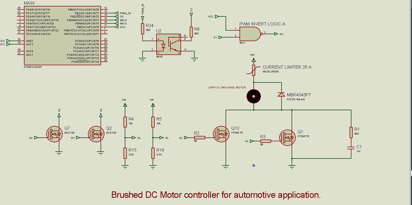
DC AUTOMOTIVE CONTROLLER
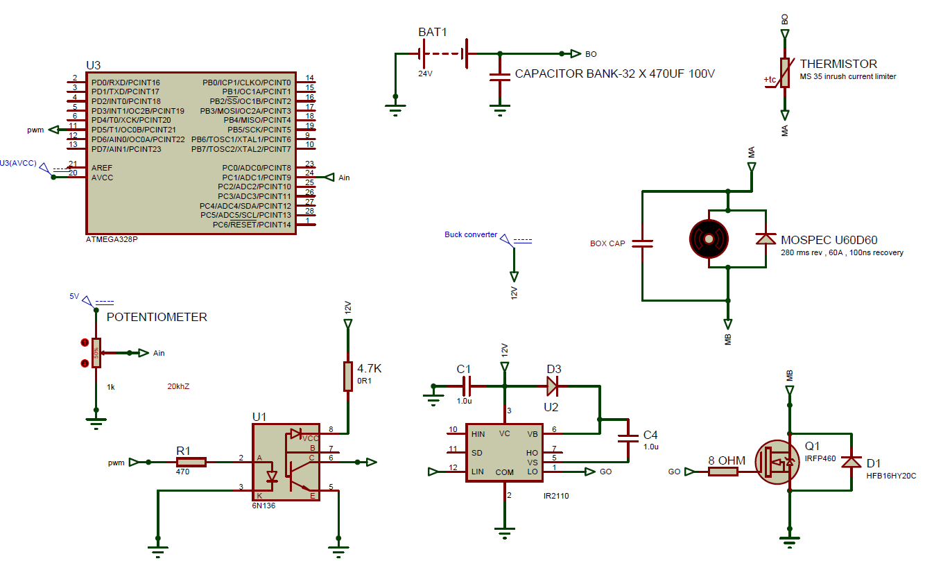
The new update has pwm frequency of 30khz with drivers capable of driving mosfets at high speed and a rise time of 50ns at gate of power mosfet.Fast opto also enable isolation of controller.The power mosfet is replaced with higher power and current ratings and faster flyback diodes used across motor.
Snubber box capacitors are also implemented across dc link electrolytic capacitors.
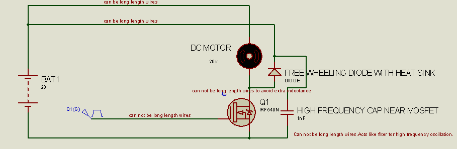
The leads of free wheeling diode are kept such that it covers max inductance of motor terminals.
When operating at high switching frequency and high power,wire inductance should be noted.Below shows one quadrant dc controller with cautions while designing the PCB.
Free wheeling diode should be placed near mosfet so that it covers max inductance length,including motor wires.
A high frequency,box capacitor should also be used as a filter for removing spikes due to left inductance.
The resistor dividor causes undesired rise and fall time in power mosfets.Hence new design is implemented to make design more reliable.
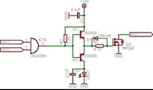
The driver consists of push pull mechanism ,controlled by pwm pulses.
The below design lacked snubber capacitors and correct pcb layout for avoiding wire inductances.
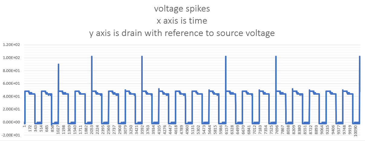
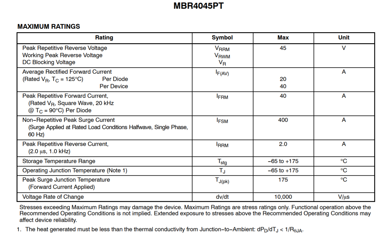
We tried this diode for free wheeling energy but it was not able to sufficiently supress voltage spikes of 100v.
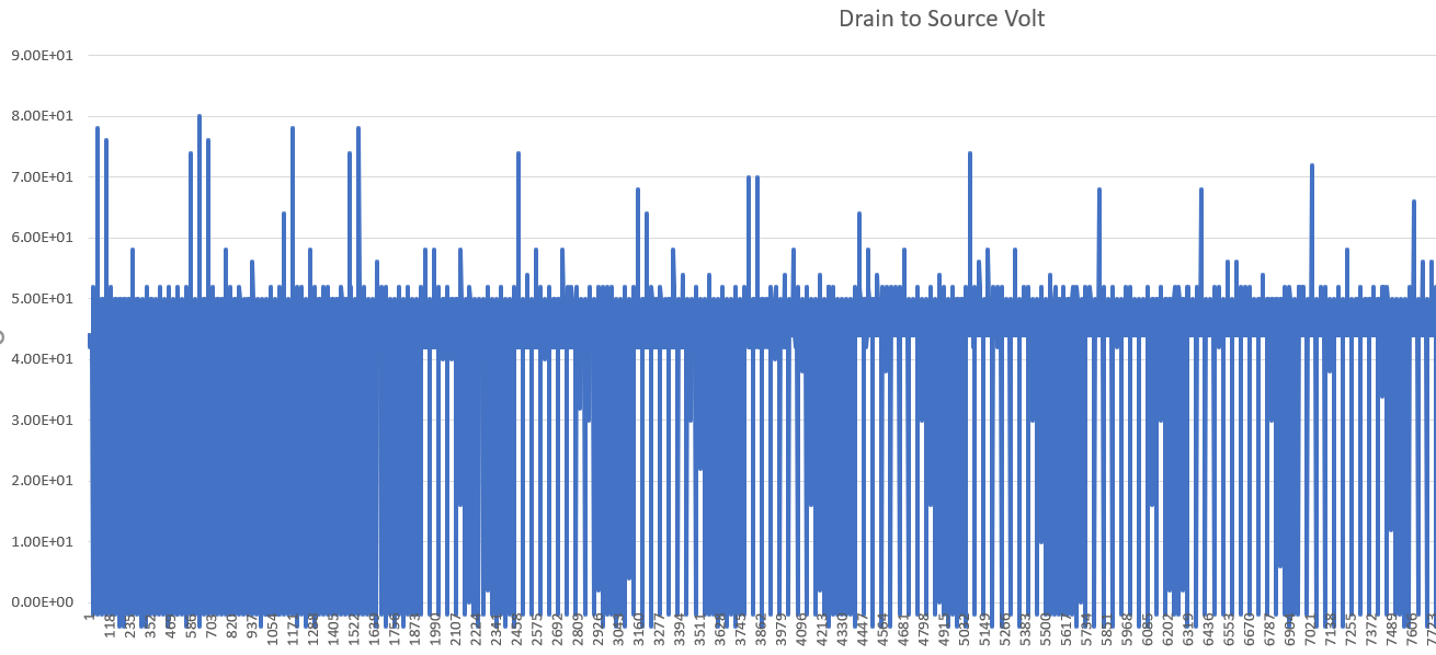
This high speed switching schottky diode were better performing in freewheeling energy and supressed voltage spikes of 100v reduces in frequency.
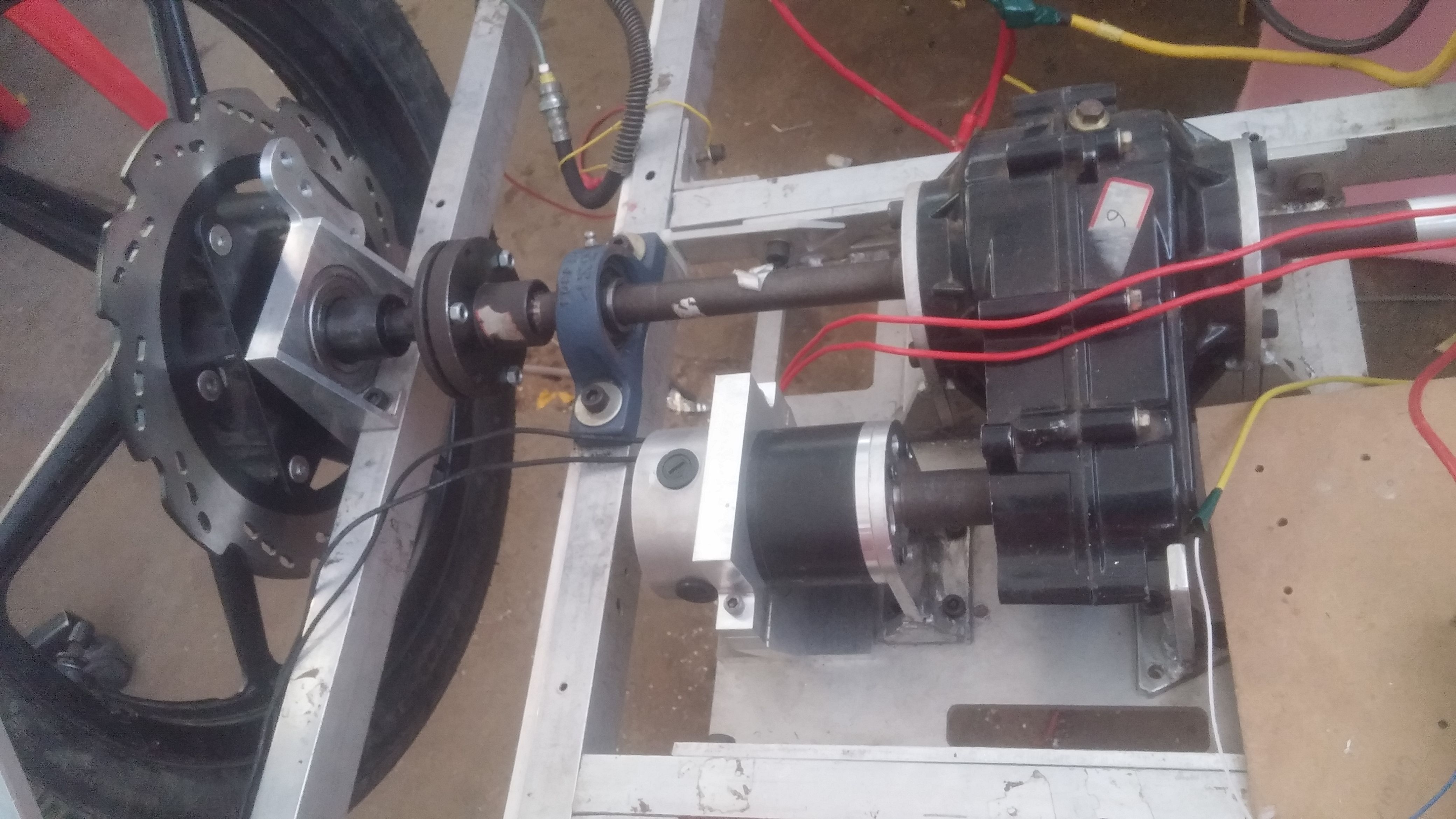
The video shows measurements while controller is used to run the car.Readings are of power mosfet drain with respect to ground .Observe the voltage spikes!